HobbyCNC
PRO Chopper Driver Board
You have now completed the basic construction of the board. Before moving on to finish the installation, we need to perform some basic tests to ensure you did not make any errors.
Do Not Install U1, U2, U3, U4, U8 and U9 until you have completed the following testing!
We need to apply power to the board at position TB6. You must supply a minimum of 12v DC, but less than 42v DC. Apply to the TB6 position at the ports labeled "+" and "–". Do not reverse the polarity when applying the power or certain destruction of various components on the board is very possible!
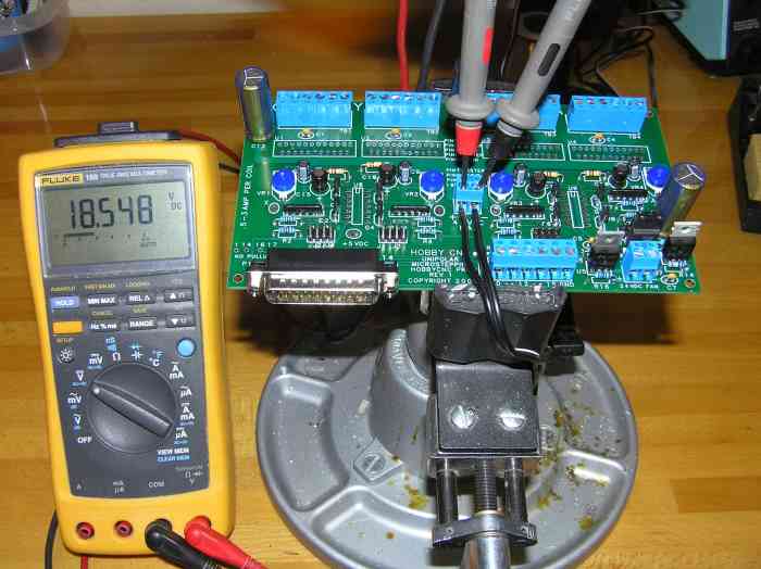
After applying 12v to 42v DC at TB6, you should verify the voltage across TB6 with a volt meter. The black lead of your meter should go to the " –" terminal and the red lead to the "+". In our test case, we have 18.548v being applied to the board.
Now we need to verify that the 5v regulator circuit is functioning as intended. The 5v circuit provides power to all the semiconductors on the board, so it is important we have the correct voltage here before installing any of the driver chips.
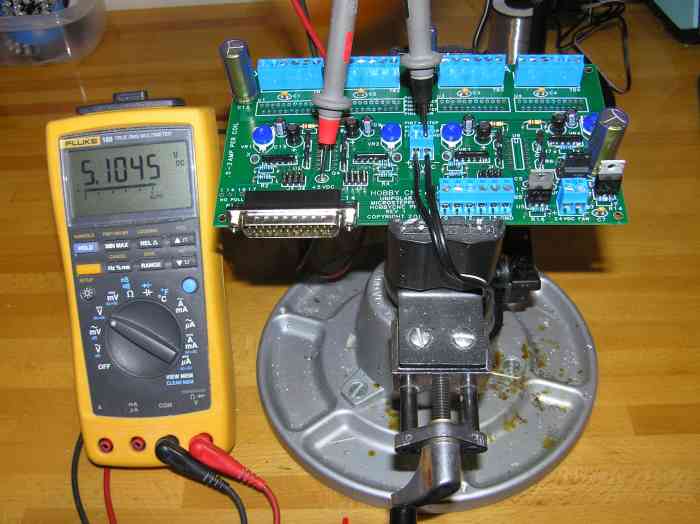
Leaving your Black volt meter probe on the " –" terminal of TB6, apply the red probe to the pad labeled "+5 VDC". The voltage here should be measured between 5.0v DC to 5.2v DC. If the voltage does not match this range, you need to go back and review your installation. Failure to ensure that you have 5.0v DC to 5.2v DC is present can very easily cause permanent damage (blow) the driver chips. If you have problems with the +5v reading, take a close look at the components at U5, R14 and R16.
In our test, we are at 5.1045v DC, which is exactly where it should be.
| Previous |
01 – 02 – 03 – 04 – 05 – 06 – 07 – 08 – 09 – 10 – 11 – 12 – 13 –
14 15 – 16 – 17 – 18 – 19 – 20 – 21 – 22 – 23 – 24 – 25 – 26 – 27 |
Next |